Slopes and Roundings
Introduction
In AnTherm elements are specified by the coordinates of their corner points – X1, X2, Y1, Y2 and in the three-dimensional case Z1 and Z2. Until now, it was only possible to specify rectangular elements. Due to the finite difference method used by AnTherm, AnTherm still effectively works only with rectangles. Nonetheless it is now possible to use slopes and roundings in AnTherm models. These shapes are approximated by rectangular, staircase-shaped elements. That means that the user enters an element that is either triangular or corresponds to a sector of an ellipse, and then this element is subdivided into several rectangular elements. The number of these rectangular elements can be defined by the user in order to achieve an optimal balance between the required precision and the speed of computation.
In order to avoid the necessity to modify the input method, we decided to add a button to the element editor which allows conversion of the current element to a slope or roundness. The coordinates of the two points entered in the element editor are interpreted as the end points of the slope or roundness. A slope is modeled as a triangle, a roundness as a sector of an ellipse. By combining several rectangular elements and converting some of them to triangles or sectors of ellipses it is possible to create shapes representing, for instance, roofs or chimneys.
Moreover, it is now possible to specify elements rotated by an angle between 0 and 90 degrees (clockwise or counter-clockwise). These elements can be rectangular or triangular. Effectively these rotated elements are approximated by several rectangular, staircase-shaped elements.
New Elements
The new feature „slopes and roundings“ permits the specification of three new types of elements. The user first has to enter the coordinates of two corner points, which has the effect that the new element is interpreted as a rectangle, and then has to click the button „Convert to Slope or Roundness“. This indicates the element not to be interpreted as a rectangle but as a different shape, to be chosen in the window that is now opened. In the most basic case, there are three possibilities:
- Slope: Slopes have the shape of a triangle.
- Roundness: Roundings have the shape of sectors of ellipses.
- Roundness Complement: These elements correspond to the difference between a sector of an ellipse and a complete rectangle.
In the most basic case the conversion results in the drawing of an element of the chosen shape instead of a rectangle. The oblique or round side of this shape is bordered by the two specified corner points.
Moreover, it is possible to draw geometric shapes that are composed of up to four oblique or round elements.
Quadrants
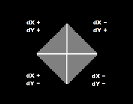
Upon conversion to a slope or roundness the element can be subdivided into up to four quadrants. Effectively up to four elements of the specified shape are drawn which are then approximated by rectangular, staircase-shaped elements. The element is always drawn in such a way that the corner point of the rectangle located in the respective quadrant is left out. So, for instance, if a slope is drawn in the top left quadrant, its endpoints are the bottom left and top right corner points of the rectangle, and the third corner point of the rectangle is the bottom right corner point of the rectangle. The top left corner point of the rectangle is left out.
The following sketch explains this principle: In this example, a square was subdivided into four quadrants and in each of these quadrants a slope was drawn.
Input
In order to enter a slope or roundness the user first has to create a new element:
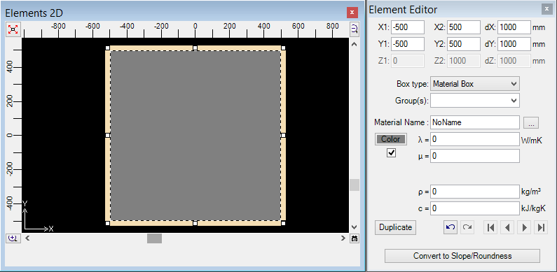
As next step the user has to click the button „Convert to Slope/Roundness“. Now the following window appears:
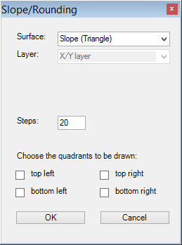
The individual components of this window are rather easy to explain:
- Shape: Slope, Roundess or Roundness Complement
- Layer: Only relevant to the three-dimensional case. Here the user specified whether the slope or roundness should appear in the X/Y layer, the X/Z layer or the Y/Z layer. If the user chooses the X/Y layer, the coordinates Z1 and Z2 remain the same for all of the elements into which the slope or roundness is subdivided. In case of a slope this results in a solid figure with the form of a prism, the base of which is located on the X/Y layer.
- Steps: Number of rectangular elements into which the slope or roundness is effectively subdivided. This number refers to a single quadrant. If you draw a shape composed of the two left quadrants, this shape will be effectively subdivided into the twofold number of steps. Choosing the two upper quadrant also results in a twofold number of rectangles. However, the number of steps effectively corresponds to the number entered as the staircase-shaped elements are vertically aligned.
- Quadrants: Here the user can choose the quadrants to be drawn. In the section „Quadrants“ the effect of this has been explained. If no quadrant is specified, the signs of dX, dY and dZ decide how the shape or roundness is drawn.
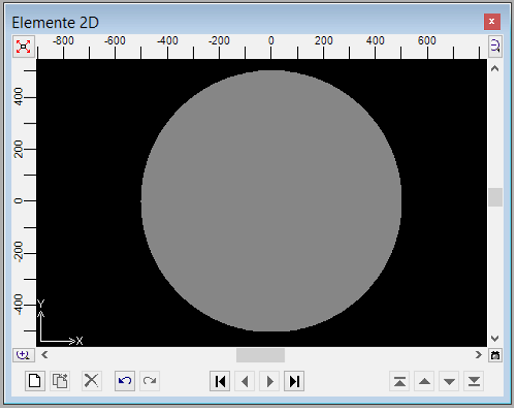
If we want to convert the square which we initially created to a circle in a high resolution, we have to make the following inputs:
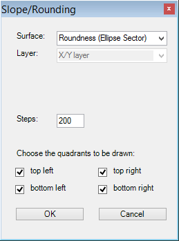
The square is thus subdivided into four quadrants in each of which a sector of an ellipse is drawn. Since the basic element is a square, which means that its width and height are identical, the resulting shape will be a circle. Choosing 200 steps results in a very high resolution (maybe even higher than necessary).
We get to see the result as soon as we click the button „OK“:
It is also easily possible to create composed shapes such as this one:
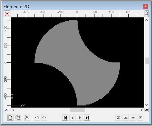
In order to create this shape we start with a square-shaped material box. We duplicate this box and convert one of the two copies to a roundness where we specify the top left and bottom right quadrants to be drawn. We then convert the other copy to the complement of a roundness and choose the top right and bttom left quadrants. Done!
Undo
It is possible to undo the entering of a slope or roundness by pressing CTRL+Z or clicking the respective button in the element window immediately after entering the slope or roundness.
Later on it is possible to remove a slope or roundness by checking the elements belonging to it in the element list (several elements can be chosen at once by pressing the SHIFT key and clicking at the same time or pressing the CTRL key and clicking at the same time) and deleting the elements by pressing the DEL key.
Rotations
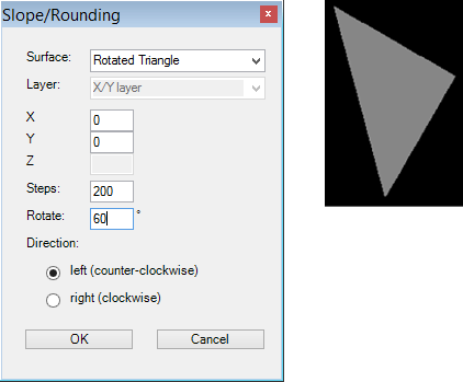
Rectangular and triangular elements can also be rotated by an angle between 0 and 90 degrees (clockwise or counter-clockwise). As an example a triangle rotated by 60 degrees is shown here.
Notes
With increasing number of steps, the precision of the calculation increases. It is recommended to use a high number of steps for optimal precision.
Long, thin elements such as heat sources or thin films require a very high number of steps. We recommend to model these elements as the last ones.
If you want to rotate several elements at once by an arbitrary angle between 0 and 90 degrees, with the rotation point being the same for all elements, it is recommended to follow these steps:
- Choose all elements you want to rotate. Click the first element, then keep the CTRL key pressed while clicking the next element and so on.
- Click an element with the right mouse button and select "Convert to Slope/Roundness" in the context menu.
- Choose "Rotated Rectangle", enter the rotation point and either keep the number of steps suggested by AnTherm or choose a larger number, but not less than suggested.
See also: Element Editor, Context menu of element processing, Element selection window, Mirror window, Translate window, Stretch window, Rotate window