Element Editor
 The
Element Editor window provides a central input function of construction input.
Depending on the
type of input or edited element
different input fields are activated or shown.
The
Element Editor window provides a central input function of construction input.
Depending on the
type of input or edited element
different input fields are activated or shown.
Note: You shall switch between input fields by using the TAB-key. Using that key confirms the data entry. On the other hand it provides a good alternative compared to permanent mouse use.
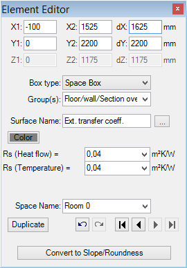
The Element Editor window displays data of a element currently selected for editing in the element list. The selection can be taken within element selection window and/or in Elements 2D window.
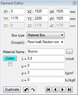
The input of coordinate positions x1,x2,y1,y2,z1,z2 of element's box is common to all element types. Coordinate input is done in millimetres. The input can also be given by the entry of the first coordinate and of the related thickness interval dX, dY, or dZ - the other (second) coordinate will by recalculated accordingly when the input field is being left (e.g.. by pressing the TAB-key).
Also, regardless of element's type, each element can be assigned to one or more groups for simplifying selections.
By assigning names to space boxes (or Power Source boxes) you will define boundary conditions for the calculation model.
During the input material
boxes and
space boxes it is advised
to use a an earlier prepared
materials list and
surface list. These windows
"cooperate" with Element Editor when used in context of assigning
material- or surface properties to the box - a double-click onto a
material's line of materials list
(or surface line of surfaces list)
or a drag-drop of one line onto Element
Editor window results in an assignment of chosen properties thus eliminating
further need of (possibly repetitive) input of those.
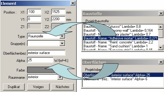
Both windows (the
materials list or
surfaces list) can be opened by
clicking the "..." button placed to the right of material's (or
surface's) name field.
Remark: A drag-drop of a material or surface (from a
materials list or
surface list) onto the Element-Editor
is only allowed if there are elements of corresponding type (material
box or surface box) selected.
Remark: Assigning material properties can be done from the materials database window too (by a drag-drop or by a double-click).
Pressing a right mouse button over Element Editor window exposes (possibly comprehensive) context menu of element processing which provides further editing functions. This context menu and functions provided by is it are common to all element editing windows and described separately.
| Input fields | Are used to input detailed
data of one element - see below. |
| New Duplicate |
Inserts a new Element (of the
Type "Empty")
at the end of the element
list (or creates a duplicate of the element currently selected). Remark: When this button is shown focused one can use the ENTER key to activate it instead of the mouse. Remark: Holding SHIFT-key while that button is depressed will additionally swap coordinates of the duplicate. |
 Undo Undo(Ctrl-Z) |
Undoes (reverts) the latest action(s) in the given
editing context. |
 Redo Redo(Ctrl-Y) |
Redoes (reapplies) the action lately undone in the given editing context. |
|
|
Selects the first element in the element list. |
| Selects an element which is previous to the currently selected in the element list. | |
| Selects an element which is next to the currently selected in the element list. | |
|
|
Selects the last element in the element list. |
| Click right mouse button | Exposes the
context menu of
element processing functions or
group editing functions. |
 Button "..." Button "..." |
Clicking onto the button "..." adjacent to
material (or surface) name field exposed the window of
surfaces or
materials. |
| Double-click onto field label | A double-click over the coordinate field label (left to the input
field) will swap the coordinates (value of the first
coordinate will be moved to the second field and the one of the second to the
first) - eventually useful in context of the Duplicate
function. A double-click onto a label of a material or surface property fields (left to the input field) exposes the surfaces window or materials window . |
| Drag-drop of a material / surface line | A drag-drop of a material or surface (from a materials list or surface list) onto the Element-Editor results in an assignment of chosen properties thus eliminating further need of (possibly repetitive) input of those. |
Input fields
Note: You shall switch between input fields by using the TAB-key. Using that key confirms the data entry. On the other hand it provides a good alternative compared to permanent mouse use.
| Position x1, x2, y1, y2, z1, z2 Extent dX, dY, dZ |
The input of coordinate positions x1,x2,y1,y2,z1,z2 of
element's box is common to all
element types. Coordinate input is done in millimetres.
The input can also be given by the entry of the first coordinate and of the
related extent dX, dY, or dZ - the other (second) coordinate will by
recalculated accordingly when the input field is being left (e.g.. by
pressing the TAB-key).
Remark: A double-click over the field label (left to the input field)
will swap the coordinates (value of the first coordinate
will be moved to the second field and the one of the second to the first) -
eventually useful in context of the Duplicate
function. |
| Type | Defines the
Type of an element:
The meaning of various kinds of elements is described further below here. Remark: While this input field is shown focused one can use arrow keys or type the first letter of type on the keyboard (E, M, S, P) to select the type from the list. |
| Group(s) | Enables an assignment of an element to one or more
groups. Remark: Pressing the right mouse button when the pointer if over this field will expose the context menu of group editing functions |
Specific to material elements: |
|
| Material name | Name of material. It is used for documentation purpose. Important: Leading and trailing spaces are significant only during data entry. That white space will be dropped and ignored during the creation of the calculation model. Names differing only by the number of leading or trailing spaces are significant and considered as different materials only during data entry (e.g. Materials list, Data Entry report) but not within Modelling Report nor calculation model. |
| λ (lambda) | Defines the Thermal Conductivity of the material. Remark: Each change to this input field results in automatic colouring of the element (simple inserting of a space character at the end of lambda value followed by pressing TAB key will result in calculation of new colour). Remark: To calculate an equivalent thermal conductivity of small air cavities (as it is common in window frames or perforated bricks) there is the Air Cavity calculator tool provided within the application. Remark: A double-click over the field label (left to the input field) will expose materials window. Remark: The equivalent heat conductivity of small air cavities and air gaps can be calculated with the air cavity calculator tool. |
| μ (my) |
Remark: A double-click over the field label (left to the input field) will expose materials window. |
| ρ (rho) |
Defines the
mass density of the material. Remark: A double-click over the field label (left to the input field) will expose materials window. |
| c (ce) |
Defines the
heat capacity of the material. Remark: A double-click over the field label (left to the input field) will expose materials window. |
|
Colour and AutoColour |
Provides the ability to assign a distinctive colour to the
element identifying it in graphical views and evaluations. To select the colour click onto the coloured rectangle labelled "Colour" - it will expose colour selection dialog. Remark: By default the colour is automatically assigned when change to lambda value is applied, based on predefined colour table. Removing the checkmark will turn the "auto-colour by lambda" application setting off thus assigned colour will be retained during changes to the value of lambda. |
Specific to surface elements: |
|
| Surface name | Name of the surface property. It is used for documentation
purpose. Remark: A double-click over the field label (left to the input field) will expose surfaces window. Important: Leading and trailing spaces are significant only during data entry. That white space will be dropped and ignored during the creation of the calculation model. Names differing only by the number of leading or trailing spaces are significant and considered as different surfaces only during data entry (e.g. Surface list, Data Entry report) but not within Modelling Report nor calculation model. |
| RS |
Defines the Thermal Transfer Resistance of the
surface.
This is an alternative input to α . Remark: A double-click over the field label (left to the input field) will expose surfaces window. Remark: From AnTherm version 8.131 on, two different RS values can be entered for heat flows and temperatures. They are used for the respective calculations. Remark: From AnTherm version 10 you can change RS for several room cells. To do this, select the corresponding room cells in the element selection. Click the right mouse button, there you find the function Change RS. Click again, it opens another window where you can change the RS. |
| α (alpha) | Defines the Thermal Transfer Coefficient of the
surface.
This is an alternative input to RS . Remark: A double-click over the field label (left to the input field) will expose surfaces window. See also: Application setting "Alpha (surface transmittance) hidden" |
| Space name | Name of the space. It represents distinct
boundary condition. Remark: The name can be selected from a list of already known space names. While this input field is shown focused the known name can be chosen by using arrow keys or by entering the keyboard key of the first letter in the space name. Important: It is mandatory to assign a distinct name. An empty entry will be automatically replaced by the space named "NONE". Important: Leading and trailing spaces are significant only during data entry. That white space will be dropped and ignored during the creation of the calculation model. Names differing only by the number of leading or trailing spaces are significant and considered as different space names only during data entry (e.g. Data Entry report) but not within Modelling Report ,calculation model nor within thermal conductance report, results report etc. |
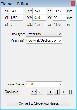
Specific to power source elements: |
|
| Power source name | Name of a power source to be assigned to material extent
covered by this element. It represents distinct
boundary condition. Remark: The name can be selected from a list of already known power source names. While this input field is shown focused the known name can be chosen by using arrow keys or by entering the keyboard key of the first letter in the power source name. Important: It is mandatory to assign a distinct name. An empty entry will be automatically replaced by the power source named "NONE". Important: Leading and trailing spaces are significant only during data entry. That white space will be dropped and ignored during the creation of the calculation model. Names differing only by the number of leading or trailing spaces are significant and considered as different power source names only during data entry (e.g. Data Entry report) but not within Modelling Report ,calculation model nor within thermal conductance report, results report etc. |
Element type (kind/type of a element)
The Material Box (material element)
A material box is a extent of a volume filled with some specific material. Heat transport within material is described by thermal conductivity of material assigned to the box. Vapour transport by diffusion within material is described by its vapour diffusion resistance number. The dynamic, transient behaviour of the material regarding its ability to store heat is given by its mass density and heat capacity.
Remark: The equivalent heat conductivity of small air cavities and air gaps can be calculated with the air cavity calculator tool.
The Space Box (space element, space air)
A space box represents an air filled room of some defined temperature. The heat transport occurs only at surfaces of material boxes connected to the space.
All space boxes assigned same space name are merged together as one space. Each such space will later be assigned to one temperature (the boundary condition) during the simulation and evaluation. By consequently choosing respective space names – e.g. exterior, room, kitchen, bath – or – e.g.. Room 0, Room 1, … - one creates a list of boundary conditions for simulations.
Important: It is mandatory to assign a distinct name. An empty name will be automatically replaced by the space named "NONE".
The Power Source (PowerBox, power element, energy source or sink region/area)
A power source generates no new volume box. Contrary to material boxes it only defines an area (cube) of power source or power sink. All material boxes covered by this are (or their parts) will be assigned to that power source and will receive heat energy from this source.
All power source boxes assigned same name are grouped together as one power source. Each such source will later be assigned to one power density (the boundary condition) during the simulation and evaluation. By consequently choosing respective power source names – e.g. heating interlayer, wall heating, power stick – or – e.g.. PS 0, PS 1, … - one creates a list of boundary conditions for simulations.
Important: It is mandatory to assign a distinct name. An empty name will be automatically replaced by the power source named "NONE".
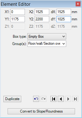
The Empty box (EmptyBox, empty element, adiabatic element, deleting/erasing/adiabatic box)
Empty boxes are primarily used to excavate or cut areas of the construction creating adiabatic boundaries. A metaphor to „Vacuum“, without any kind of heat transport, can be helpful.
Group(s) of Elements
Each one element can be assigned to one or more group names. Elements can then be quickly selected by the group name - see element list and the context menu of element processing functions.
The assignment of an element to some group is done by entering the group name into the group name input filed. Names of groups the element is already assigned to can be listed by clicking onto the arrow symbol adjacent to the input field. While this input field is shown focused one can use arrow keys to browse through the list.
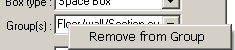 The
click with the right mouse button of the input filed Group(s) exposes the
context menu of group
editing functions.
The
click with the right mouse button of the input filed Group(s) exposes the
context menu of group
editing functions.
| Remove from Group | The Element will be removed from the group actually displayed in the input field |
Boundary conditions
All space boxes merge by their name together to spaces. Every space is assigned one temperature (the boundary condition) during the simulation. By consequently choosing respective space names – e.g. exterior, room, kitchen, bath – or – e.g.. Room 0, Room 1, … - one creates a list of boundary conditions for simulations.. Same applies to power sources.
All spaces (their temperatures) and all power sources (their power densities) provide boundary conditions for results calculated by the program collectively. The name of a space or a power source uniquely identifies such boundary condition which is then further processed and used during Evaluation.
If the particular space- or power source name is already known one can click onto the arrow adjacent to the name input field and select it directly from the list exposed. While the name input field is shown focused one can use arrow keys to select the name or type the first letter of the name in the list.
Important: It is mandatory to assign distinct names for spaces and power sources. An empty name will be automatically replaced by the power source named "NONE".
Important: The component prepared for the calculation must contain two boundary conditions at least - see: Solver window - data integrity and messages.
See also: Element selection window, Elements 2D, Elements 3D, Materials window, Surfaces window, Element kinds/types, Context menu of element processing, Colour settings file LambdaToColor.ColorList, Coordinate system, Air Cavity Calculator (Tool)