3D Navigation within 3D windows
The imagery displayed in three dimensional rendering views can be controlled in various ways:
- With the mouse
- By keyboard shortcuts
- With 3D control panel (within Results3D window)
In addition immersive stereo display rendering in various technologies can be requested.
3D Navigation with the mouse
Graphics shown within 3D windows (Elements 3D, Results 3D) can be manoeuvred in virtual 3D space (rotation, translation or scaling) with the mouse easily. The level of display detail will be reduced during the motion if required.
Remark: When the mouse pointer is located above some special objects within the view these objects can be specifically controlled directly in different manner then described here (e.g. position of the movable colour bar, moveable probe point X,Y,Z, moveable orientation marker).
| Place the mouse pointer over graphics view of the window: | |
Left mouse key, drag: |
A dragging action (holding down the left mouse button, then moving the mouse) rotates the view in 3D space. The view behaves as if it were attached to a virtual trackball whose centre is at the centre of the view window. The mouse cursor is attached to the part of the trackball that protrudes above the surface of the window. Similarly the view follows a virtual joystick held with the mouse while joystick behaviour is activated instead. You can switch between trackball- and joystick behaviour with keyboard controls. |
| Ctrl + mouse wheel turn Hold the Ctrl key and turn the mouse wheel or: Ctrl + left mouse button, drag:Hold the Ctrl key and press and hold the left mouse button, move the mouse pointer. |
The 3D view is rotated around the axis in the geometrical
centre of the view and perpendicular to the screen surface (rotation
around the block axis, also called "Rolling"). You will need this function to flip the view "upside down" for example. |
| Shift + left mouse button, drag: Hold the Shift key and press and hold the left mouse button, move the mouse pointer. |
The view is translated in the plane of the window following the mouse pointer (translation, scrolling, panning in the view plane). |
| Mouse wheel turn or: Shift + Ctrl + left mouse button, drag: or: Right mouse button, drag: |
The view is scaled (zoom-in and zoom-out).
Scaling operation is executed relative to the geometrical centre of the 3d view in virtual space |
|
|
The position and scaling of the view will be adjusted in such a way, that the whole building component fits into the view. |
|
|
Resets the camera (viewer) position to its default state:
Scaling of the view is adjusted accordingly to fit the whole component into the view. |
See also: Elements 3D, Results 3D, Evaluations and Results, 3-D Navigation (control panel), TrackBall Rotation
3D Navigation with the keyboard
Graphics shown within 3D windows (Elements 3D, Results 3D) can be manoeuvred in virtual 3D space (rotation, translation or scaling) with the keyboard. Further settings of the displayed graphics can also be controlled and adjusted with the keyboard.
| Click once with the mouse onto the graphics part of the window to move the keyboard focus to it. | |
| Keyboard key | Function |
|---|---|
| T | Trackball Interactor of the mouse - dragging the mouse controls the moves of the 3d view |
| J | Joystick Interactor of the mouse - the position of the mouse in the view controls the direction and the speed of continuous movements |
| P | Perspective On/Off |
| L | More Light On/Off |
| F | Fit (also "NumPad 5") |
| + (Plus) | Scale (Zoom) +10% (also "Numpad +") |
| − (Minus) | Scale (Un-Zoom) -10% (also "Numpad −") |
| Ins | Side view from the left |
| Del | Side view from the right |
| Home | Side view from the front |
| End | Side view from the back |
| Page-Up | Side view from the top (also "Enter") |
| Page-Down | Side view from the bottom |
| Enter | Side view from the top (also "Page-Up") |
| Remark: Hold one of the modifier keys (Alt, Ctrl or Shift) depressed while pressing the button to view animated transformation of the position. The duration of the animation is set via the advanced application setting "DesiredFlyToSeconds". | |
| Numpad 5 | Fit (also "F") |
| Numpad + | Scale (Zoom) +10% (also +, Plus) |
| Numpad − | Scale (Un-Zoom) -10% (also −, Minus) |
| Numpad 6 | Rotate to the right around the vertical axis, Azimuth -10° (also Right-Arrow) |
| Numpad 4 | Rotate to the left around the vertical axis, Azimuth +10° (also Left-Arrow) |
| Numpad 8 | Rotate upwards around the horizontal axis, Elevation -10° (also Up-Arrow) |
| Numpad 2 | Rotate downwards around the horizontal axis, Elevation +10° (also Down-Arrow) |
| Numpad 9 | Rotate to the right/upwards around a diagonal axis, Azimuth/Elevation, 7,07°/7,07° |
| Numpad 7 | Rotate to the left/upwards around a diagonal axis, Azimuth/Elevation, 7,07°/7,07° |
| Numpad 1 | Rotate to the left/downwards around a diagonal axis, Azimuth/Elevation, 7,07°/7,07° |
| Numpad 3 | Rotate to the right/downwards around a diagonal axis, Azimuth/Elevation, 7,07°/7,07° |
| Ctrl + Numpad 6 | Roll to the right around the view (block) axis, -10° (also Ctrl + Right-Arrow) |
| Ctrl + Numpad 4 | Roll to the left around the view (block) axis, +10° (also Ctrl + Left-Arrow) |
| Ctrl + Numpad 8 | Roll to the right around the view (block) axis, -10° (also Ctrl + Up-Arrow) |
| Ctrl + Numpad 2 | Roll to the left around the view (block) axis, +10° (also Ctrl + Down-Arrow) |
| Shift + Numpad 6 | Translate (scroll, pan) to the right, -10 pixels (also Shift + Right-Arrow) |
| Shift + Numpad 4 | Translate (scroll, pan) to the left, +10 pixels (also Shift + Left-Arrow) |
| Shift + Numpad 8 | Translate (scroll, pan) upwards, -10 pixels (also Shift + Up-Arrow) |
| Shift + Numpad 2 | Translate (scroll, pan) down, +10 pixels (also Shift + Down-Arrow) |
| Shift + Numpad 9 | Translate (scroll, pan) diagonal to the right and upwards by 10 pixels |
| Shift + Numpad 7 | Translate (scroll, pan) diagonal to the left and upwards by 10 pixels |
| Shift + Numpad 1 | Translate (scroll, pan) diagonal to the left and down by 10 pixels |
| Shift + Numpad 3 | Translate (scroll, pan) diagonal to the right and down by 10 pixels |
| Right-Arrow | Rotate to the right around the vertical axis, Azimuth -10° (also Numpad-6) |
| Left-Arrow | Rotate to the left around the vertical axis, Azimuth +10° (also Numpad-4) |
| Up-Arrow | Rotate upwards around the horizontal axis, Azimuth -10° (also Numpad-8) |
| Down-Arrow | Rotate downwards around the horizontal axis, Azimuth +10° (also Numpad-2) |
| Ctrl + Right-Arrow | Roll to the right around the view (block) axis, -10° (also Ctrl + Numpad-6) |
| Ctrl + Left-Arrow | Roll to the left around the view (block) axis, +10° (also Ctrl + Numpad-4) |
| Ctrl + Up-Arrow | Roll to the right around the view (block) axis, -10° (also Ctrl + Numpad-8) |
| Ctrl + Down-Arrow | Roll to the left around the view (block) axis, +10° (also Ctrl + Numpad-2) |
| Shift + Right-Arrow | Translate (scroll, pan) to the right, -10 pixels (also Shift + Numpad-6) |
| Shift + Left-Arrow | Translate (scroll, pan) to the left, +10 pixels (also Shift + Numpad-4) |
| Shift + Up-Arrow | Translate (scroll, pan) upwards, -10 pixels (also Shift + Numpad-8) |
| Shift + Down-Arrow | Translate (scroll, pan) down, +10 pixels (also Shift + Numpad-2) |
| Shift + Home | Translate (scroll, pan) to the left by 2/3 of the full window width |
| Shift + End | Translate (scroll, pan) to the right by 2/3 of the full window width |
| Shift + Page-Up | Translate (scroll, pan) upwards by 2/3 of the full window height |
| Shift + Page-Down | Translate (scroll, pan) down by 2/3 of the full window height |
| S |
Provides switching between monocular view (standard) and several stereo viewing (binocular) modes.
The setting change will be confirmed with a dialog message displayed. Remark: Eventually additional hardware and license extensions might be required. Remark: This setting requires a valid license feature STEREO3DVIEW Remark: This function will have no effect if there are no stereo modes available. |
Immersive stereo display rendering techniques
By default 3D renderings are provided for monocular view onto 3D objects projected onto the display (monitor) plane either with or without perspective transformations.
Binocular viewing is accomplished by providing different images to the left and right eye thus allowing for immersive depth perception. Some of the techniques require only very simple additional equipment. Others have more sophisticated technical prerequisites which must be fulfilled to use them.
| Implementation provided monocular and binocular rendering modes | |||
| mono (no stereo) |
Monocular view (standard). |
True Color | No additional equipment required |
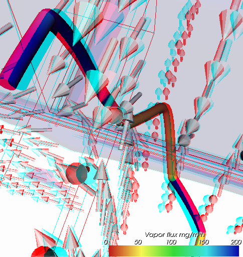
| Anaglyph (Red/Cyan) |
By using simple Red/Cyan Glasses the effect of true depth can be accounted. Remark: By adjusting the anaglyph color mask different color filter glasses can be used. The anaglyph color saturation can be adjusted too. |
Some Color | Red/Cyan glasses required |
| Red/Blue | By using simple Red/Blue Glasses the effect of true depth can be accounted at the cost of colour quality (the image will be seen in levels of gray). | Monochrom | Red/Blue glasses required |
| Dresden | For output to a Dresden-style display. | True Color | Dresden type interlaced display required |
| VRex (Interlaced) | For output to a VRex stereo projector. All of the odd horizontal lines are from the left eye, and the even lines are from the right eye. The user has to make the render window aligned with the VRex projector, or the eye will be swapped. | True Color | Interlaced VRex type projector required |
| Checkerboard | For output to a checkerboard style display. | True Color | Checkerboard type interlaced display required |
| Crystal Eyes | Active stereo-mode display. | True Color | Crystal Eyes type display and active 3D shutter glasses required |
| Left Eye (mono) Right Eye (mono) |
Images shown in mono which shall be directed to the left and right eye respectively can be used to create binocular views based on those two images but in some other stereo viewing application. | True Color | No additional equipment required |
| STEREO3D-option: Stereoscopic, binocular display of three dimensional evaluations is is only possible with an active STERO3DVIEW-Option of the program. |
 |
Remark: Activating any binocular stereo modes will have no effect if there are no stereo modes available.
Remark: Only passive stereo view types can be copied into the clipboard or image file. Disabling of stereo mode is only required for hardware dependant stereo types.
Remark (technical): The anaglyph color saturation factor ranges from 0.0 to 1.0: 0.0 means that no color from the original object is maintained, 1.0 means all of the color is maintained. The default value is 0.65 and can be changed within application settings. Too much saturation can produce uncomfortable 3D viewing because anaglyphs also use color to encode 3D.
Remark (technical): The anaglyph color mask values are two numbers which are bits mask that control which color channels of the original stereo images are used to produce the final anaglyph image. The first value is the color mask for the left view, the second the mask for the right view. If a bit in the mask is on for a particular color for a view, that color is passed on to the final view; if it is not set, that channel for that view is ignored. The bits are arranged as r, g, and b, so r = 4, g = 2, and b = 1. By default, the first value (the left view) is set to 4, and the second value is set to 3. That means that the red output channel comes from the left view, and the green and blue values come from the right view. This can be changed within application settings.
See also: Elements 3D, Results 3D, Evaluations and Results, 3-D Navigation (control panel), TrackBall Rotation